- 您现在的位置:买卖IC网 > Sheet目录868 > LTM4604IV#PBF (Linear Technology)IC DC/DC UMODULE 4A 66-LGA
�� �
�
�LTM4604�
�PIN� FUNCTIONS�
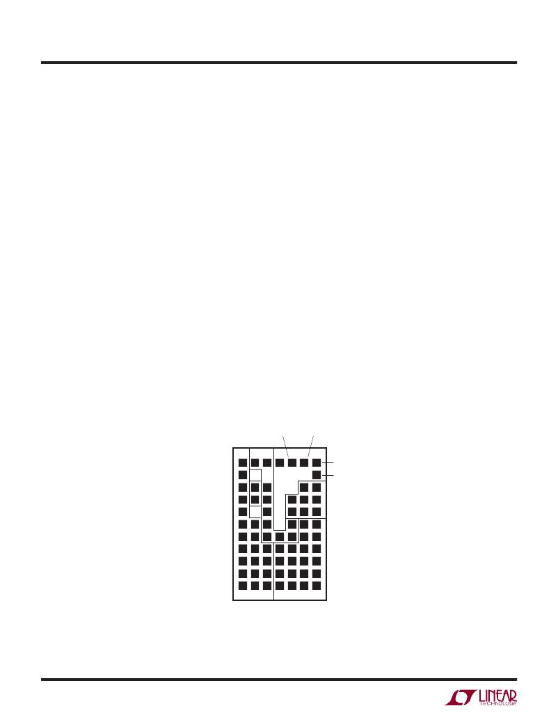
�V� IN� (B1,� C1,� C3-C7,� D7,� E6� and� E7):� Power� Input� Pins.�
�Apply� input� voltage� between� these� pins� and� GND� pins.�
�Recommend� placing� input� decoupling� capacitance� directly�
�between� V� IN� pins� and� GND� pins.�
�V� OUT� (D8-D11,� E8-E11,� F6-F11,� G6-G11):� Power� Output�
�Pins.� Apply� output� load� between� these� pins� and� GND� pins.�
�Recommend� placing� output� decoupling� capacitance� directly�
�between� these� pins� and� GND� pins.� Review� Table� 4.�
�GND� (G3-G5,� F3-F5,� E4-E5,� A1-A11,� B6-B11,� C8-C11):�
�Power� Ground� Pins� for� Both� Input� and� Output� Returns.�
�TRACK� (E1):� Output� Voltage� Tracking� Pin.� When� the� module�
�is� con?gured� as� a� master� output,� then� a� soft-start� capaci-�
�tor� is� placed� on� the� RUN/SS� pin� to� ground� to� control� the�
�master� ramp� rate.� Slave� operation� is� performed� by� putting�
�a� resistor� divider� from� the� master� output� to� ground,� and�
�connecting� the� center� point� of� the� divider� to� this� pin� on�
�the� slave� regulator.� If� tracking� is� not� desired,� then� connect�
�the� TRACK� pin� to� V� IN� .� Load� current� must� be� present� for�
�tracking.� See� Applications� Information� section.�
�FB� (G2):� The� Negative� Input� of� the� Error� Ampli?er.� Inter-�
�nally,� this� pin� is� connected� to� V� OUT� with� a� 4.99k� precision�
�resistor.� Different� output� voltages� can� be� programmed�
�with� an� additional� resistor� between� FB� and� GND� pins.�
�Two� power� modules� can� current� share� when� this� pin� is�
�connected� in� parallel� with� the� adjacent� module’s� FB� pin.�
�See� Applications� Information� section.�
�COMP� (G1):� Current� Control� Threshold� and� Error� Ampli?er�
�Compensation� Point.� The� current� comparator� threshold�
�increases� with� this� control� voltage.� Two� power� modules�
�can� current� share� when� this� pin� is� connected� in� parallel�
�with� the� adjacent� module’s� COMP� pin.�
�PGOOD� (F1):� Output� Voltage� Power� Good� Indicator.� Open-�
�drain� logic� output� that� is� pulled� to� ground� when� the� output�
�voltage� is� not� within� ±7.5%� of� the� regulation� point.�
�RUN/SS� (D1):� Run� Control� and� Soft-Start� Pin.� A� voltage�
�above� 0.8V� will� turn� on� the� module,� and� below� 0.5V� will�
�turn� off� the� module.� This� pin� has� a� 1M� resistor� to� V� IN� and�
�a� 1000pF� capacitor� to� GND.� See� Application� Information�
�section� for� soft-start� information.�
�SW� (B3� and� B4):� Switching� Node� of� the� circuit� is� used� for�
�testing� purposes.� This� can� be� connected� to� copper� on� the�
�board� to� improve� thermal� performance.� Make� sure� not� to�
�connect� it� to� other� output� pins.�
�TOP� VIEW�
�TRACK�
�PGOOD�
�A�
�B�
�C�
�D�
�E�
�F�
�G�
�V� IN�
�1�
�COMP�
�2�
�3�
�SW�
�RUN/�
�SS�
�GND�
�FB�
�4�
�5�
�6�
�7�
�8�
�9�
�10�
�11�
�GND�
�V� OUT�
�4604fa�
�6�
�发布紧急采购,3分钟左右您将得到回复。
相关PDF资料
LTM4605EV#PBF
IC DC/DC UMODULE 5A 141-LGA
LTM4606MPV#PBF
IC DC/DC UMODULE 6A 133-LGA
LTM4607IV#PBF
IC BUCK/BOOST SYNC ADJ 5A 141LGA
LTM4608AEV#PBF
IC BUCK SYNC ADJ 8A 68LGA
LTM4608IV#PBF
IC DC/DC UMODULE 8A 68-LGA
LTM4609IV#PBF
IC BUCK/BOOST SYNC ADJ 4A 141LGA
LTM4612IV#PBF
IC BUCK SYNC ADJ 5A 133LGA
LTM4613MPV#PBF
IC UMODULE DC/DC 8A 133-LGA
相关代理商/技术参数
LTM4604IV#PBF
制造商:Linear Technology 功能描述:IC SWITCH MODE DC/DC POWER SUPPLY LGA-66
LTM4604IVPBF
制造商:Linear Technology 功能描述:Conv DC-DC Single-Out Step Down
LTM4604IV-PBF
制造商:LINER 制造商全称:Linear Technology 功能描述:Low Voltage, 4A DC/DC μModuleTM with Tracking
LTM4604V
制造商:LINER 制造商全称:Linear Technology 功能描述:Low Voltage, 4A DC/DC μModuleTM with Tracking
LTM4605
制造商:LINER 制造商全称:Linear Technology 功能描述:High Effi ciency Buck-Boost DC/DC μModule
LTM4605EV#PBF
功能描述:IC DC/DC UMODULE 5A 141-LGA RoHS:是 类别:电源 - 板载 >> DC DC Converters 系列:µModule® 设计资源:VI-200, VI-J00 Design Guide, Appl Manual 标准包装:1 系列:* 类型:隔离 输出数:1 电压 - 输入(最小):66V 电压 - 输入(最大):160V Voltage - Output 1:12V Voltage - Output 2:- Voltage - Output 3:- 电流 - 输出(最大):* 电源(瓦) - 制造商系列:50W 电压 - 隔离:* 特点:* 安装类型:通孔 封装/外壳:9-FinMod 尺寸/尺寸:4.60" L x 1.86" W x 0.79" H(116.8mm x 47.2mm x 20.1mm) 包装:散装 工作温度:-25°C ~ 85°C 效率:* 电源(瓦特)- 最大:*
LTM4605EV#PBF
制造商:Linear Technology 功能描述:IC SMPS CONTROLLER CURRENT-MODE LGA
LTM4605EVPBF
制造商:Linear Technology 功能描述:Conv DC-DC Step Up Step Down